Anderson / Separator Vessels / Centrifugal Separators / Centrifugal Receiver Separators
Anderson Centrifugal Receiver Separators
LRH · LRV · LRU
Anderson Centrifugal Receiver Separators are high-capacity gas-liquid separators that remove bulk liquid, mist, and entrained contaminants from air, gas, steam, and vapor lines. These receiver-style separators combine centrifugal separation with receiver sump capacity to help protect compressors, dryers, filters, valves, regulators, controls, and downstream process equipment from liquid carryover, slugging, corrosion, fouling, and performance loss.
Switch between LRH, LRV and LRU in the left panel. Drag to orbit, scroll to zoom. Cutaway and colour key isolate parts; Play walkthrough steps the principle of operation.
LIVE 3D SECTION
Designed for
Designed for large-volume gas streams with heavy liquid loading, Anderson Centrifugal Receiver Separators are ideal where a standard inline separator may not provide enough liquid holding capacity. They are purpose built for critical gas, steam, and process applications where entrained liquids must be removed before storage, compression, conditioning, or processing.
Product configurations
LRH. Horizontal receiver separator for installations requiring horizontal vessel orientation and high liquid storage volume.
LRV. Vertical down receiver separator for applications requiring vertical installation and efficient liquid collection.
LRU. Vertical up-flow receiver separator for systems where up-flow orientation best supports piping layout and separation requirements.
Custom options: Carbon steel, stainless steel, or application-specific alloy construction; flanged or welded connections; manual drain, automatic float drain, or condensate management connections.
Key points of differentiation
High liquid capacity. Receiver-style vessel design provides added sump volume for bulk liquid removal and surge conditions.
Low operating costs. Mechanical centrifugal separation operates with no moving parts or replaceable filter media, minimizing maintenance.
Low pressure drop. Carefully guided flow supports high-capacity separation with minimal system resistance.
Rugged construction. ASME-quality pressure vessel fabrication supports demanding industrial and process service.
Flexible integration. Multiple configurations help fit compressor skids, gas conditioning packages, steam systems, and plant utility lines.
Applications
Anderson Centrifugal Receiver Separators are applied wherever high-volume gas, steam, air, or vapor streams carry significant liquid or solid entrainment. Their combination of efficient mechanical separation and generous receiver capacity makes them well suited for protecting downstream equipment, managing liquid surges, and supporting reliable operation in demanding industrial and process systems.
Natural gas production, gathering, transmission, and distribution
Compressor station inlet protection
Upstream protection for dryers, filters, coalescers, and gas conditioning equipment
Steam, air, gas, and vapor distribution lines
Primary knockout or receiver vessels in high-capacity systems
Refining, petrochemical, and chemical processing
Power generation and gas turbine protection
Industrial gas, utility plant, and manufacturing facility service
OEM compressor skids, EPC-designed gas networks, and packaged process systems
Principle of operation
Anderson Centrifugal Receiver Separators use a four-step mechanical separation process designed to remove entrained liquids and solids from the gas stream.
Velocity Drop and Initial Gravity Separation. As the process stream enters the larger receiver chamber, its velocity drops sharply. The reduced carrying force allows much of the heavier entrained liquid and solid material to disengage from the gas stream and fall directly toward the drain or receiver sump under gravity.
Impingement. Remaining entrained droplets and particles strike internal surfaces, lose momentum, and coalesce into larger droplets that are more readily separated from the gas stream.
Centrifugal Force. The gas is directed into a cyclonic path. Centrifugal force drives the remaining liquid and solid particles outward against the vessel wall, separating them from the cleaned gas stream.
Gravity Drainage. Separated material flows down the vessel walls into the receiver sump, where it is collected safely and held for drain-off. This receiver-type design provides ample storage capacity for entrainment before drainage.
SPECIFICATIONS
Efficiency
99% of entrainment ≥ 10 microns
Operating Envelope
Standard configurations: up to 150 PSIG at 500°F or 300 PSIG at 500°F, depending on flange rating
Can be designed for higher pressure and temperature requirements
ASME Section VIII, Division 1 pressure vessel construction
Service Media
Suitable for gas, steam, air, and vapor services
VARIABLES
Sizes
2-1/2" - 12" standard
Larger, custom sizes are available
Materials
Carbon Steel
Stainless Steel (optional)
Connections/Mounting
Flanged
Application-specific nozzle arrangement
Orientation
Side In – Top Out (LRU)
Side In - Side Out (LRH)
Top In - Side Out (LRV)
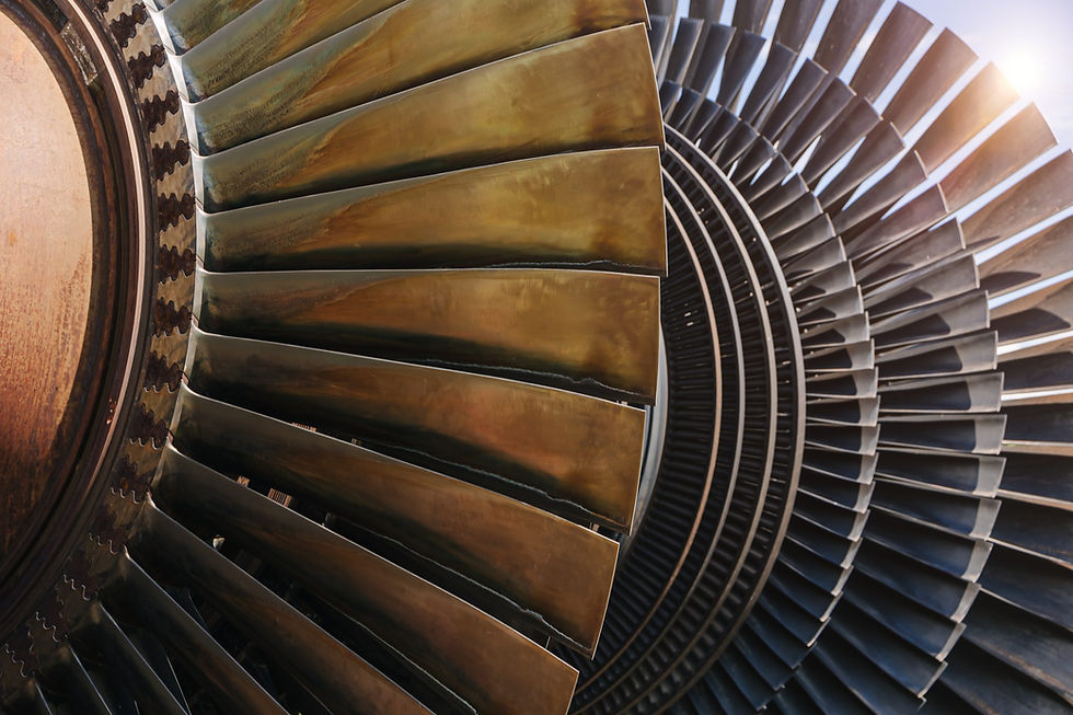
Suited for high-volume streams that carry significant entrainment
Their combination of efficient mechanical separation and generous receiver capacity makes them well suited for protecting downstream equipment, managing liquid surges, and supporting reliable operation in demanding industrial and process systems.
